U-4100 Dual Beam Spectrophotometer
The U-4100 dual beam spectrophotometer uses two different lamps to cover a wide range of wavelengths. For the deep UV, the U-4100 uses a deuterium lamp and switches to a tungsten lamp for UV, visible, and near IR measurements. The layout of the U-4100 includes monochromators, beam splitters, mirrors, focusing lenses, and detectors which can be used to analyze liquid or solid samples. Specifically, we obtained percent reflectance values for the wavelength range of 250-2500 nm and used a 5 percent reflectance standard (SRS-05) obtained from Labsphere Inc. to calculate the absolute reflectance of our samples. Below we will give descriptions of our experimental setup as well as the procedure we followed for measuring the reflectance of our samples.
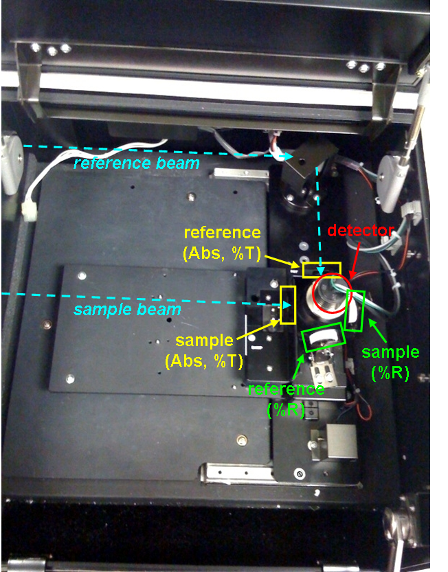
Below is the experimental setup of the Hitachi High-Tech U-4100 UV-Visible-NIR Spectrophotometer used at the MCF at Texas A&M. The reference and test sample are placed in the 6 o’clock and 3 o’clock positions of the integrating sphere respectively. The U-4100 and all its experimental parameters are controlled by the program UV Solutions through the computer in the MCF.
Procedure
- Set up parameters using the UV Solutions menu. Most of our parameters are the same as in the MCF handout for the U-4100 (linked here), but a complete list of our parameters are here.
- Collect a baseline measurement. This measurement records the reflectance of a reference substance and uses this as a baseline value to give relative (ratio) measurements of our samples. In our case, the baseline measurement was taken with BaSO4 wafers (~100% reflectance) in both the reference and sample slots of the dual beam spectrophotometer.
- Record calibration measurement of SRS-05.
- Record measurement of test sample in the 3 o’clock position of the integrating sphere.
- Data analysis and computation of absolute reflectance values using the calibration and sample measurements.
Data Analysis
- Using a spreadsheet, we compared the SRS-05 MCF reflectance values to the Labsphere provided values. Take the ratio of the two SRS-05 (MCF/Labsphere) values and divide each sample’s MCF reflectance value by this ratio at the appropriate wavelengths.
- To see the reflectance profile, plot these new absolute reflectance values versus wavelength.