HETDEX VIRUS
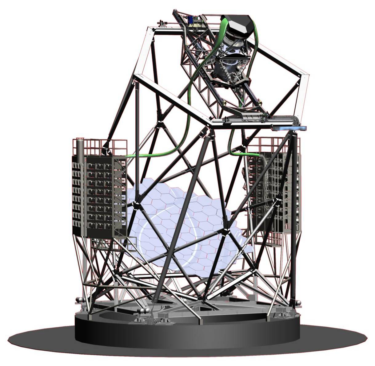
Table of Contents
The Visual Integral-Field Replicable Unit Spectrograph (VIRUS) instrument is an array of 156 identical fiber fed optical spectrographs designed to support observations for the Hobby-Eberly Telescope Dark Energy Experiment (HETDEX). The collimator subassemblies of the instrument were assembled in a production line by undergraduate students in our lab, and the enclosure was designed and built by our lab.
As of May 2021, 74 of the VIRUS IFUs are attached to spectrograph units. This number is considered complete for the purposes of the HETDEX survey, but the final four units will be brought on line as they become available.
VIRUS Collimators
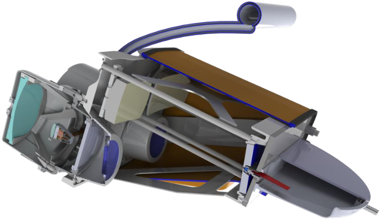
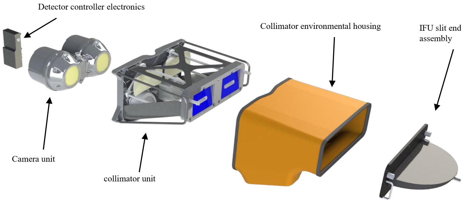
The VIRUS instruments are composed of a main spectrograph body (referred to as the “collimator”) and a vacuum vessel which houses the Schmidt camera. A volume phase holographic (VPH) grating provides a wavelength range of 350 < λ < 550 nm. Each spectrograph is fiber-fed from the focal plane of the HET via an IFU which delivers 224 fibers to each spectrograph. The fibers are laid out in a grid pattern in the telescope focal plane. This instrument design allows large-scale spectroscopic mapping of the sky.
The spectrographs are constructed in pairs, so the VIRUS instrument has 78 pairs of spectrographs.
Design
To facilitate the assembly line-style production of this unique instrument, the optical and mechanical components of VIRUS were carefully designed to ensure that the instrument was both affordable and able to be constructed in a reasonable amount of time by undergraduate students in our lab.
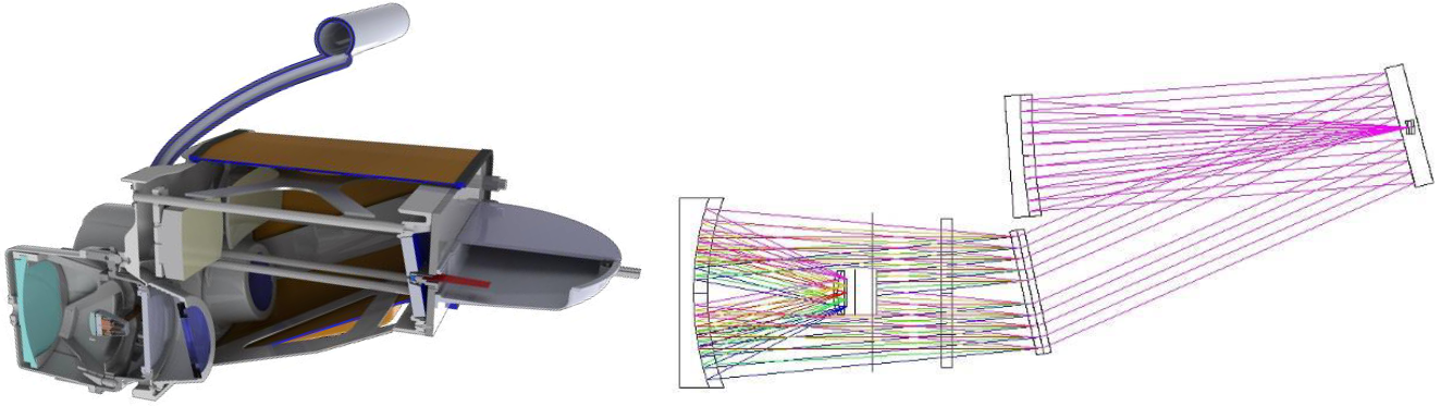
The optical design of a VIRUS unit spectrograph is a simple off-axis Schmidt collimator coupled with a traditional Schmidt vacuum camera. The VIRUS collimator has three optics: a spherical collimator mirror, a folding flat, and a volume-phase holographic (VPH) grating. These optics proved to be relatively straightforward to manufacture by many vendors.
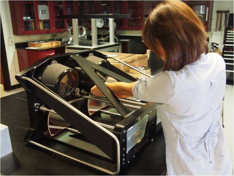
Installation of optics
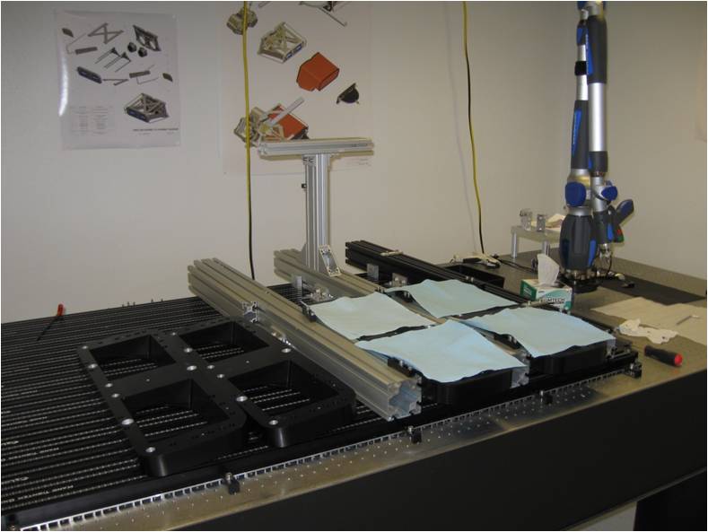
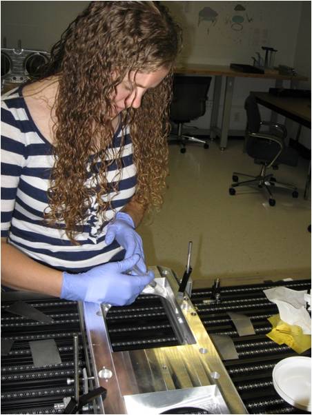
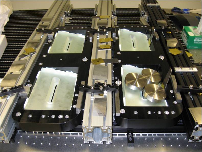
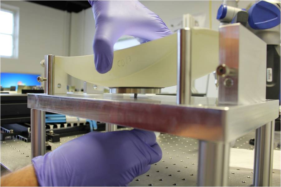
The VIRUS collimator mirror, fold flat, and grating were each installed using precision metrology equipment into a cell which was then bolted into the instrument.
An installation fixture was used to install the folding flat into the head plate. Two pairs of mirrors are installed into two head plates in one setup. The fold mirrors are precisely positioned with respect to the head plates using a Faro coordinate measuring machine (CMM) arm having a measurement accuracy of ~25 microns and are held in place with metal shims while RTV is applied around the edges of the mirror.

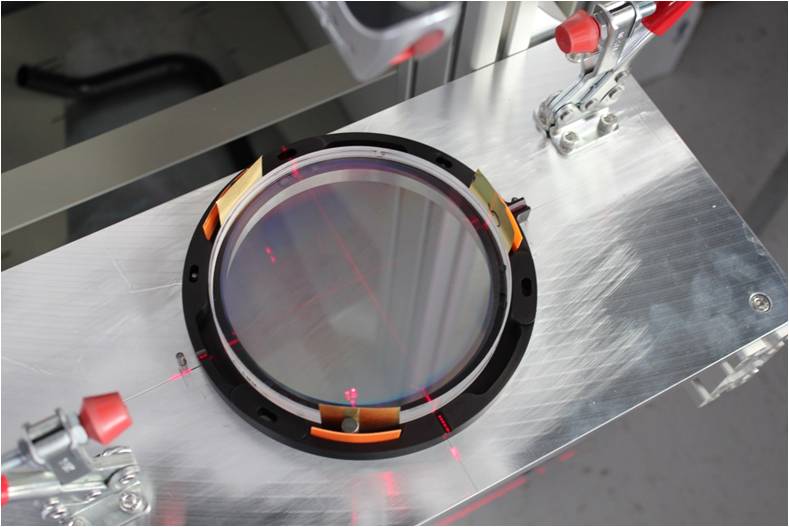
The VPH gratings were optically aligned in their cell during installation using a laser, and the internal baffles of the grating housings were installed using a fixture. The grating cell is later installed on top of the housing.
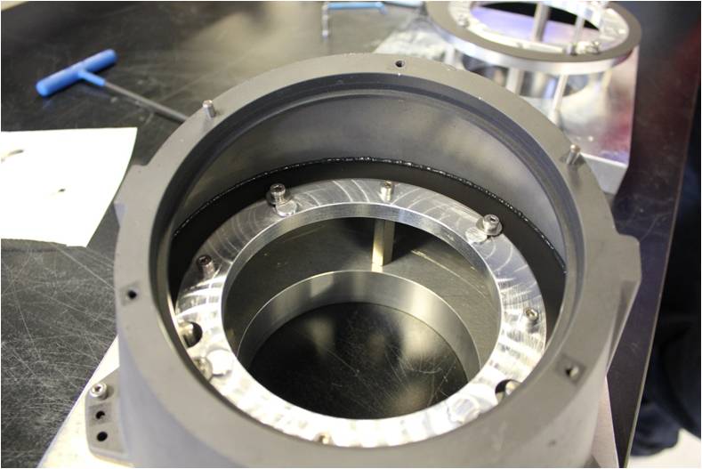
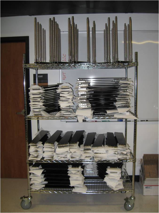
Subassembly Construction
The collimator subassemblies include the head plate which connects the collimator to the IFU fiber bundle, the base plate which connects the collimator to the camera, chassis plates that connect the head and base plate, and the collimator mirror mounting plate which is attached via Invar metering rods to the head and base plate to hold the collimator mirror in place in a temperature invariant way. All subassemblies were pre-assembled over approximately a one year period and stored before the final collimator assembly.

Final Collimator Assembly
Collimators were completed in batches of 10-15 at a time. Each set of 10-15 collimators were assembled over a 3-week period.

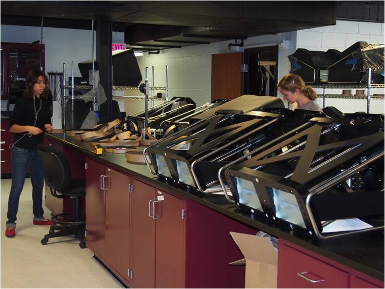
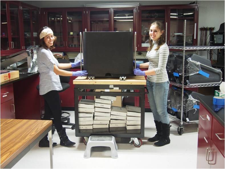
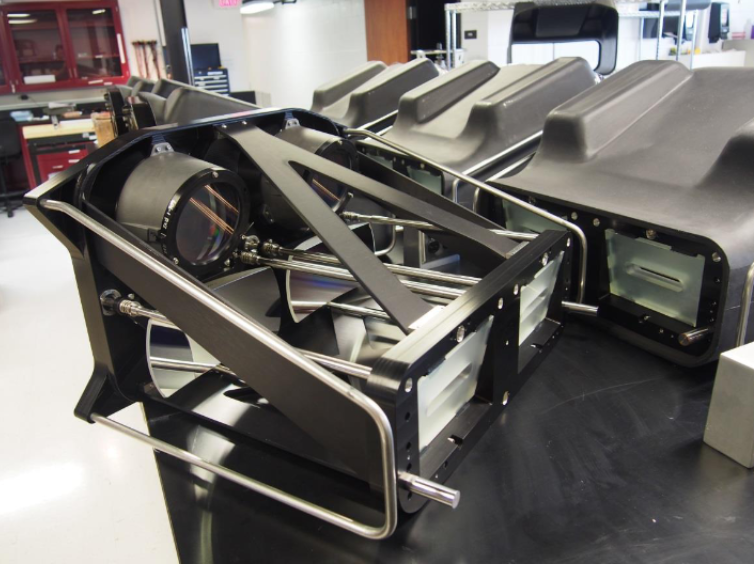
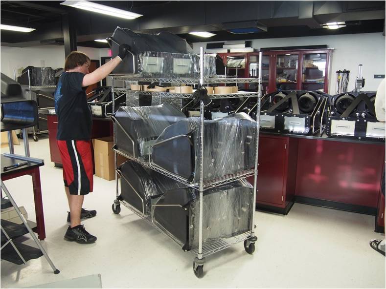
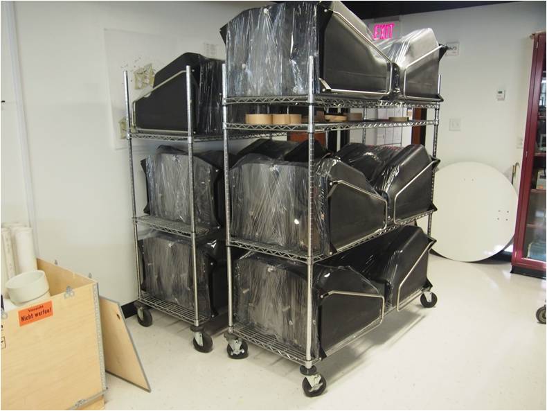
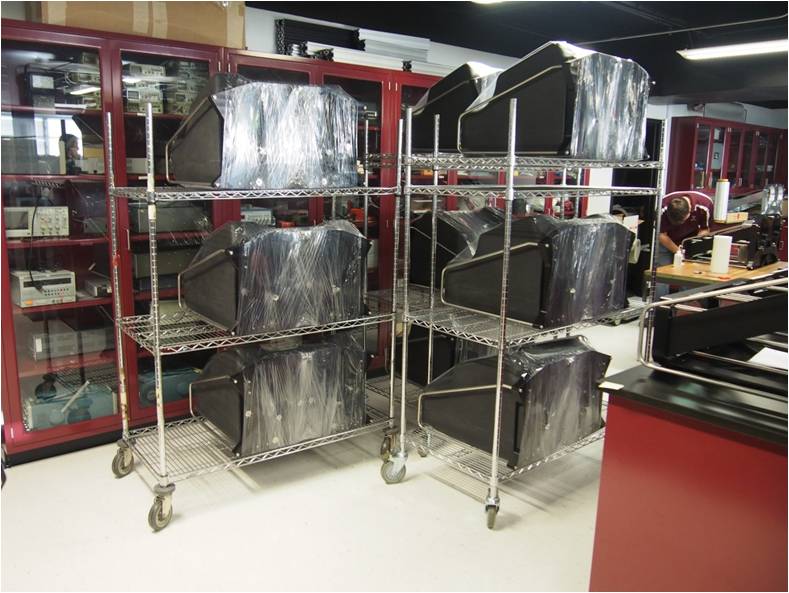
The completed collimators were fitted with a plastic cover that remains with the collimators once installed on the telescope, protected from dust with plastic wrap, and finally packaged and shipped to UT-Austin for integration with the VIRUS cameras and final optical alignment.

Virus Enclosure
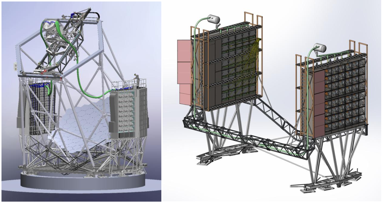
The VIRUS instrument is housed in two enclosures that are mounted adjacent to the HET via the VIRUS Support Structure (VSS). The enclosures were designed to support and protect the instrument, to enable servicing of the instrument, and to cool the instrument appropriately while not adversely affecting the dome environment. The system uses simple HVAC air handling techniques in conjunction with thermoelectric and standard glycol heat exchangers to provide efficient heat removal. The enclosures also provide power and data transfer to and from each VIRUS unit, liquid nitrogen cooling to the detectors, and environmental monitoring of the instrument and dome environments.
The two enclosure structures mount to the VSS, which is made from free-standing frames, linked together by two trusses. The VSS is isolated from the telescope structure, which ensures loads are not transferred to the telescope by the enclosures during wind gusts. During rotation, the VSS shares the HET’s azimuth drive to simplify the system, but decouples after the rotation is complete.
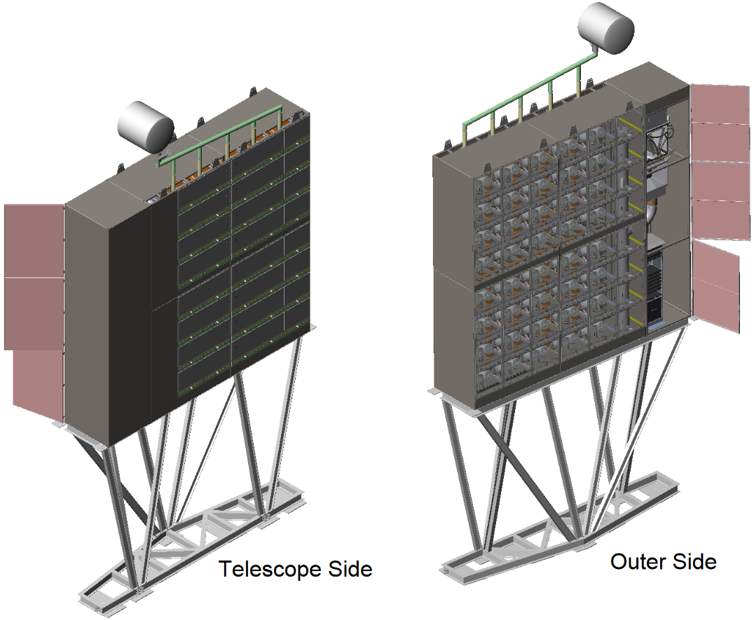
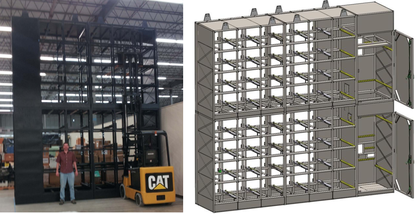
Enclosure Structure
Each enclosure structure is primarily made of 4 weldments that are bolted together to form the area that houses up to 40 VIRUS units. Two additional weldments are bolted to the side of the housing area to form the enclosure annex. The annex holds the power, control and data systems that connect to the VIRUS units. The HVAC system for the enclosure and its annex is also contained in the annex space.
The VIRUS detectors must be cooled with liquid nitrogen to achieve their science goals. Each enclosure holds a liquid nitrogen system on its roof. The liquid nitrogen is gravity fed to a manifold and flows down vertical pipes terminating with a cold finger at the location of each spectrograph pair, which is plugged into a VIRUS unit during normal operation. These tanks are refilled from a larger external tank via an automated control system.
Instrument Housing
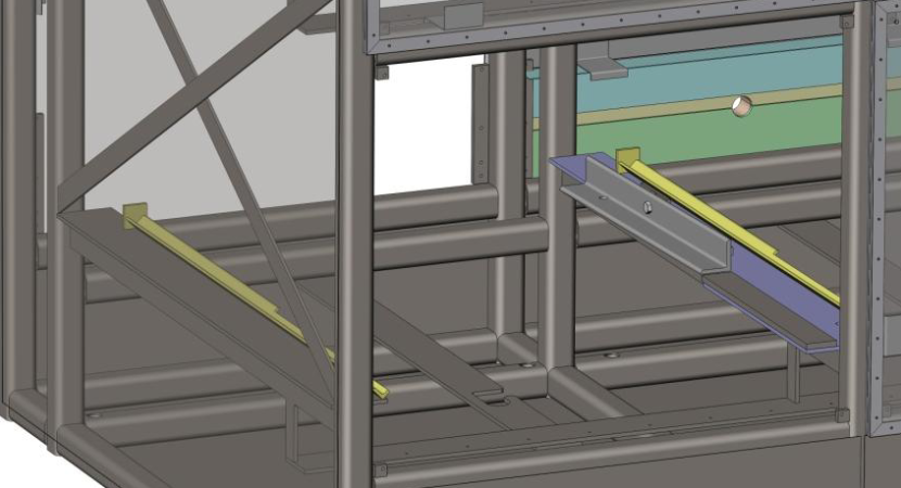
The VIRUS units have two stainless steel rails on either side that are used to support their weight. These rails are used to hold each unit within the structure using a kinematic mounting system that does not induce any stress in the VIRUS instrument. The mounting system uses a v-groove for one rail and a piece of angle iron on a fulcrum for the other. A simple zip tie is used to secure the rails so the instrument cannot slide out of the enclosure.
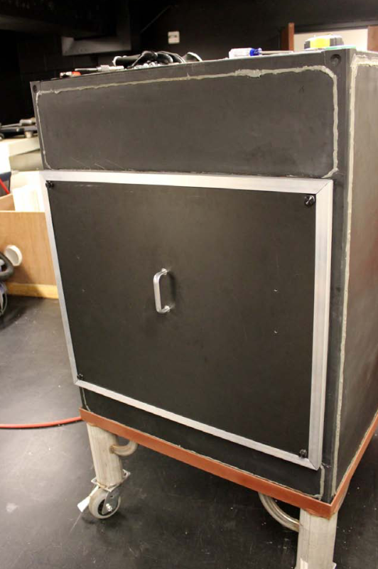
Each instrument has its own set of access doors, one that opens towards the dome and one that open towards the telescope. These doors are used to install, remove, and service the VIRUS instruments. The doors are lightweight, have captured thumb screws, are thermally insulative, and have sealed edges. The main door material is a plastic-foam composite, ensuring the doors are lightweight (2.55kg or 5.6lb) and thermally insulative. The plastic-foam composite is 23.4mm extruded polystyrene (XPS) foam that is sandwiched between two 1mm thick sheets of PVC. To protect the exposed foam faces and stiffen the edges, Al trim is glued to the outer edges. Similarly, to protect the foam around the holes, Al tubes are glued into the holes.
Thermal Management System
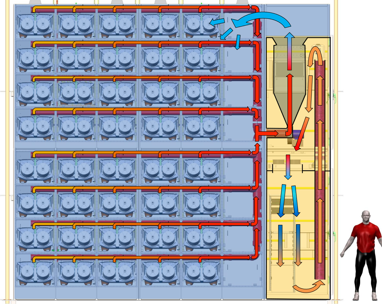
The enclosure thermal management system is designed to keep the VIRUS electronics boxes and equipment from overheating, and to prevent heat from escaping into the dome. To cool the VIRUS electronics boxes, air is sucked through the boxes via a vented duct system. This air passes through a series of fin-tube heat exchangers to cool the air to ambient temperatures and returns to the open area of the enclosure. The heat exchangers are cooled with 50/50 ethylene glycol and water (EGW), which carries the heat outside the dome. Matching the air temperature inside the enclosures to the ambient dome temperature will virtually eliminate heat transfer in or out of the enclosures.
There is an isolated cooling system for the enclosure annex. This cools the electronics used to run the VIRUS instruments as well as the enclosure air blower.
To cool the air back down to ambient temperatures, a thermoelectric cooler chills a secondary heat exchanger. This system can remove up to 600W from its process fluid and move it directly to the facility EGW. To keep the enclosure air temperature matching dome ambient, we developed a custom controller that can track the ambient temperature by iteratively calculating the TEC set point temperature.
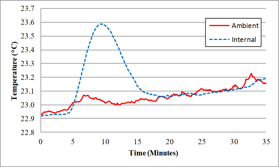
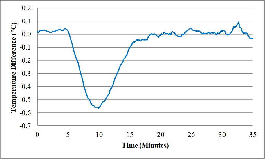
To check the validity of the controller and TEC, we set up a scaled, closed-loop HVAC system to run the TEC, controller and heat exchanger. The plot below shows the TEC & controller’s ability to track the ambient room temperature when 370W is added to the closed loop test system. It shows that after a couple of minutes the TEC was able to bring the temperature back down to the ambient temperature where it continued to match within 0.1°C.
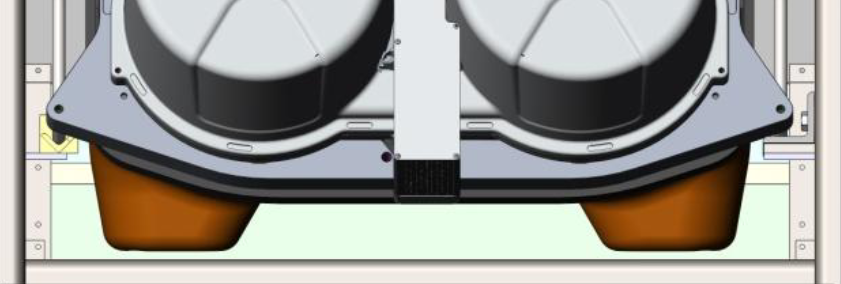
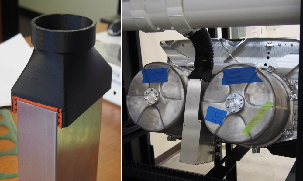
In order to attach the VIRUS electronics boxes to the ventilation system, a unique adapter had to be designed. There were no attachment hardware or features on the electronics boxes, and the airflow slots could not be obstructed. We designed an adapter that could hold onto the bare metal on the side of the box without blocking the slots. The inside of the adapter is lined with a silicon foam rubber seal that grips the box and ensures that the air flowing into the adapter is only coming from the electronics boxes.
The adapter connects to the rest of the HVAC duct work via a flexible hose. This hose allows the adapter to be moved out of the way when a VIRUS unit is added or removed from the enclosure. It also acts like a spring and pushes the adapter against the electronics box, giving it a better seal.
Publications
For more information on VIRUS and its installation in HETDEX, see our Publications.