FOCUSS

Undergraduate project: Noah Siebersma, Hudson Malone
In order for the future large, ground-based, fiber-fed astronomical spectrographs to produce quality data, the background sky spectra must be removed without compromising the target spectra. The Fiber Optic Characterization for Unprecedented Sky Subtraction (FOCUSS) project aims to automate the characterization of multiple fiber optic cables in order determine their throughput efficiency and focal ratio degradation (FRD). The throughput efficiency measures the percentage of light that enters the fiber and ends up at the detector, and the FRD test measures the angular spread of light out of the fiber as a function of incident angle.
Hardware
FOCUSS consists of a laser-driven light source, a monochromator, an integrating sphere, a photodiode, a five-axis motor for fiber positioning, and three CMOS (Complementary Metal-Oxide-Semiconductor) detectors for data acquisition.
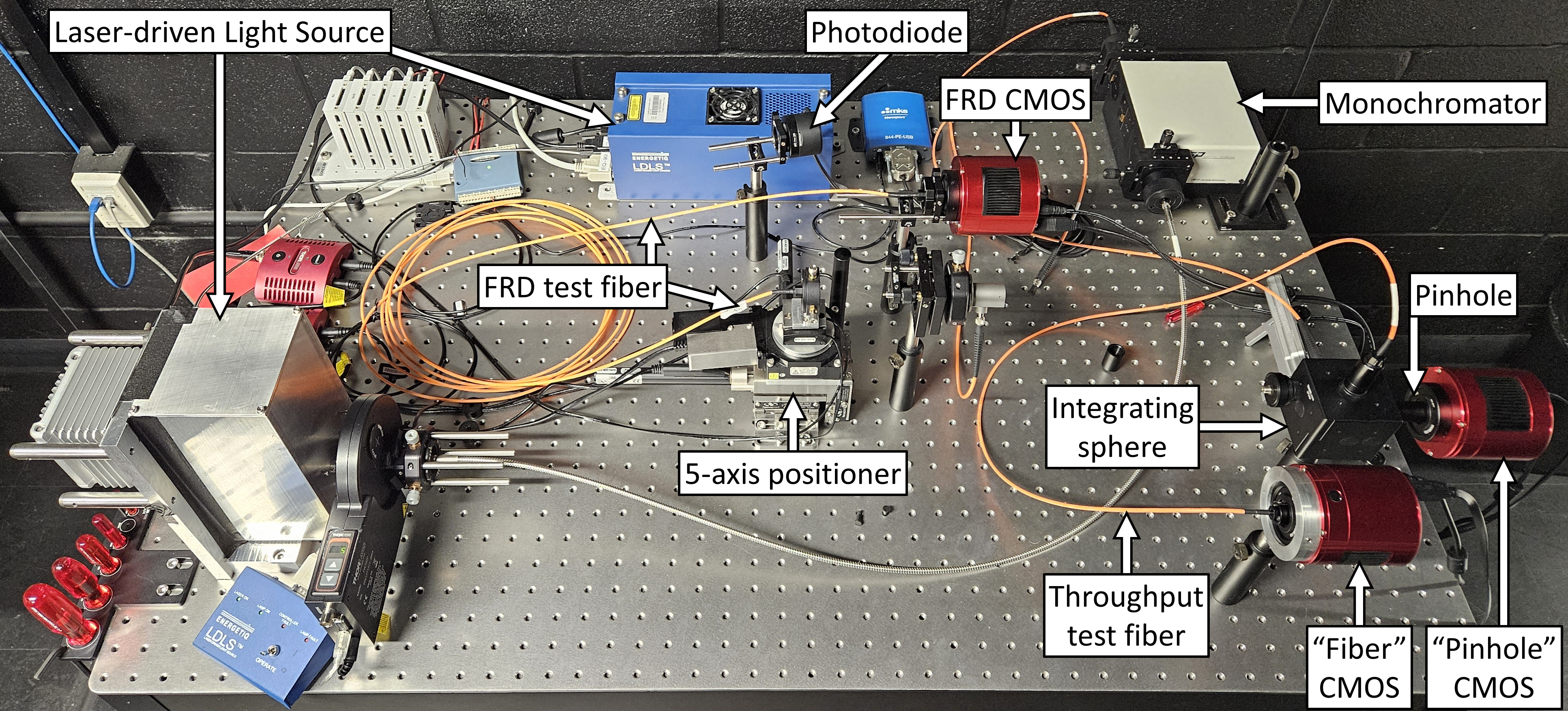
The experimental assembly in FRD test configuration, consisting of a laser-driven light source, monochromator, five-axis fiber positioner, photodiode, one CMOS detector for the FRD test, and two CMOS detectors for the throughput test, and connecting fibers.
| Device | Vendor | Model | Interface |
| Monochromator | Spectral Products | CM112 | RS232 over USB |
| Light Source | Thorlabs | SLS201L/M | N/A |
| XYZ stage | Newport | M-562F-XYZ stage with 3 CONEX- TRB12CC actuators | Conex/USB |
| ThetaY stage | Newport | CONEX-URS50BCC | Conex/USB |
| ThetaX stage | Newport | CONEX-AG-GON-UP | Conex/USB |
| Long Pass Filter Flipper | Thorlabs | MFF101/M | Manual, USB, or 0-5V TTL |
| I/O USB Interface | Measurement Computing | USB-1608FS | USB and bare wire I/O ports |
| Photodiode | Newport | 918D-UV-OD3R | DB15 to 844-PE-USB |
| Photodiode Interface | Newport | 844-PE-USB | USB or 5Hz Analog output, 0-1V |
Throughput Efficiency Characterization
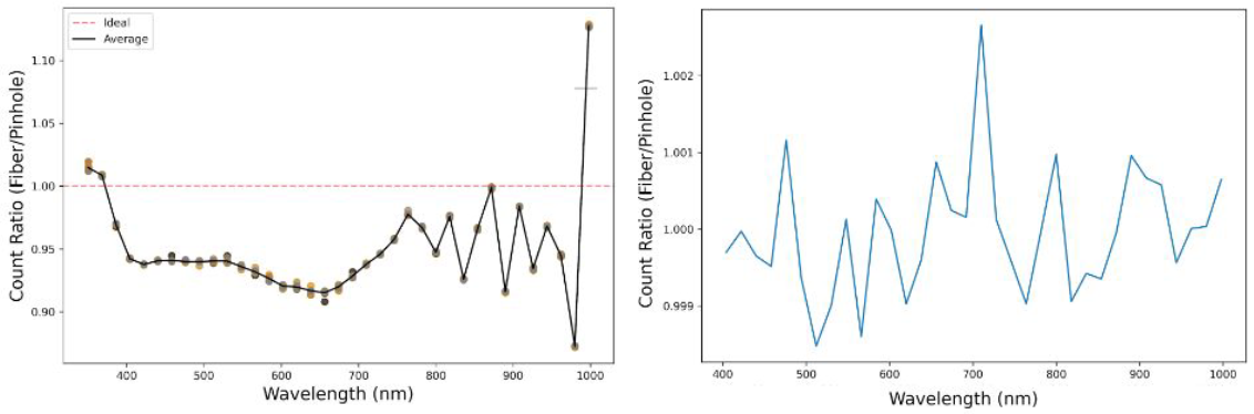
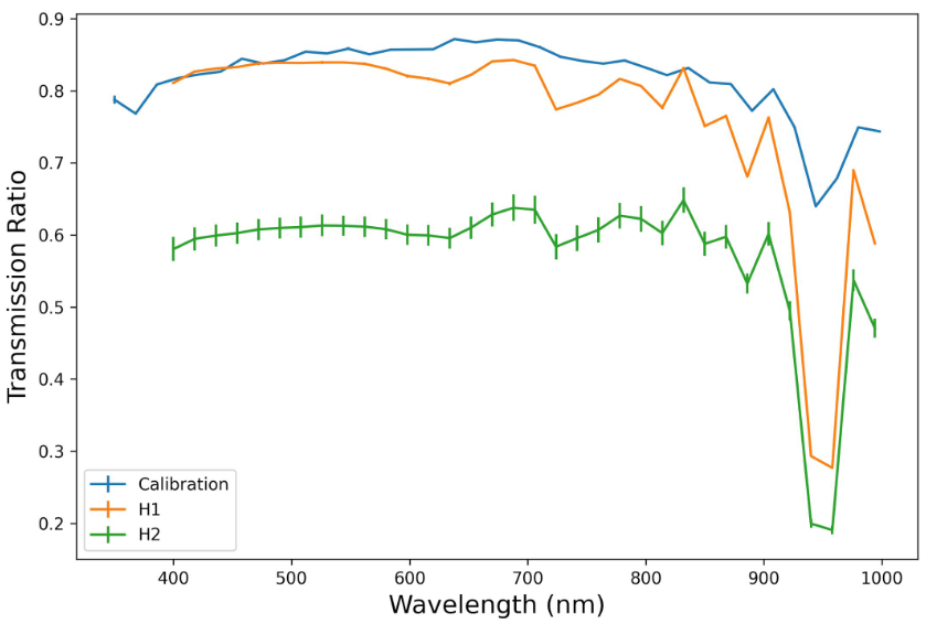
The throughput efficiency test compares the light exiting the fiber to the light entering the fiber over a range of wavelengths. A monochromator controls the light wavelength. The ratio of the transmitted light to the through light is plotted over the range of wavelengths.
A high-power boradband laser-driven light source (LDLS) emits light into a monochrometer, which isolates wavelengths for each throughput test. The light from the monochromator enters an integrating sphere, which homogenizes the input light and reduces inconsistencies. The integrating sphere has two exits, one that goes through a pinhole to a CMOS detector (the "Pinhole" detector), and one that goes through the test fiber and into a second CMOS detector (the "Fiber" detector). The light gathered by the two detectors is compared to determine the throughput efficiency of the fiber.
Calibration
Since we're comparing the light gathered from two detectors, both detectors should be calibrated to one another. To do this, a pinhole is placed in front of each detector to ensure equal light is entering both detectors, and the light counts gathered by each detector are compared. The ratio of the two detector counts give the correction factor, and this correction factor is applied to the gathered data.
Optimization
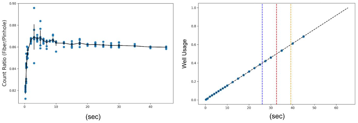
To test as many fibers as possible as quickly as possible, the duration of the total test time is taken into consideration. We optimize for the shortest exposure time while retaining high accuracy per wavelength by testing a pinhole and a known fiber and collecting ten images from multiple exposure lengths at each test wavelength. We analyze the "Fiber" to "Pinhole" detector counts ratio and analyze the well-usage, optimizing for a count ratio standard deviation 1% and/or a maximum of 40% well-usage. We are able to achieve a total test time of just over 30 minutes for a test between 350nm-998nm at 18nm step sizes and a test time of 20 minutes for a more brief test between 404nm-998nm.
Current Status
With the transmission test developed, calibrated, and optimized, we re-calibrated and began preliminary testing with our calibration fiber between wavelengths of 404nm to 998nm with stepsizes of 18nm. Since preliminary testing, we have tested our calibration fiber and two different Optran UV fiber optic cables. There is a water absorption feature between the wavelengths of 944nm to 962nm that is consistent within all fibers. We plan to control the temperature and humidity of our testing room to reduce this feature.
Focal Ratio Degradation (FRD) Characterization
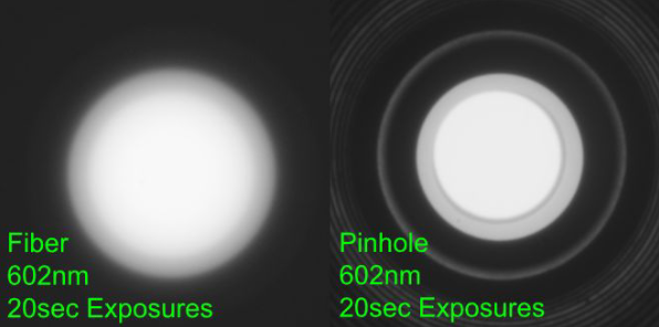
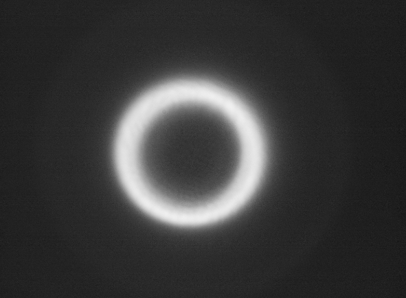
Focal ratio degradation (FRD) occurs due to small imperfections within the fiber’s core-cladding interface, called microbends, which cause the light to be scattered at a different angle than intended1. This results in an annulus, or ring shape, at the detector.
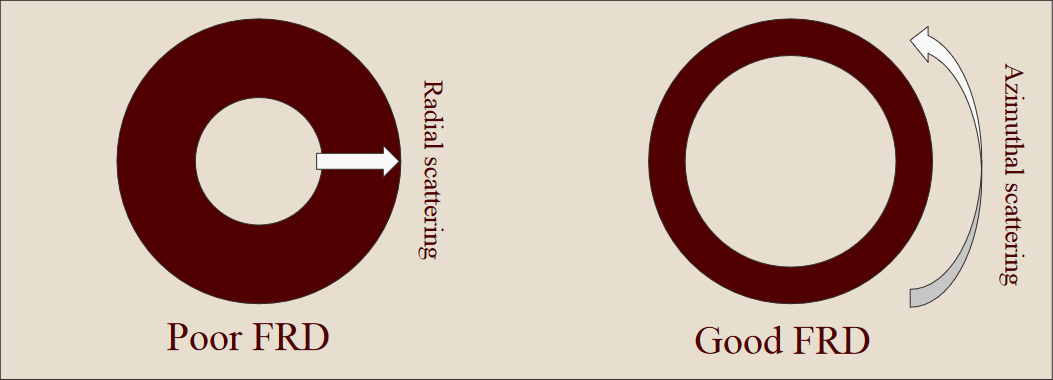
Focal ratio itself can be described as the speed of an optic, where a faster f/# implies that the light collecting area is large compared to the focal length. In this case, since the focal ratio degrades (f/# decreases) as the light travels through the fiber, the light is effectively being spread out more than expected. This results in the CMOS detector measuring fewer counts per pixel within the annulus when compared to an optical fiber with better FRD. To clarify, a fiber with poor FRD will have more light spread radially, whereas a better fiber will instead spread the light azimuthally.
Focal ratio degradation can be measured by analyzing the size and shape of the annulus, as well as the counts within. For the future of astronomical spectrographs, choosing a fiber with the best optical properties and characterizing said fiber is necessary to prevent loss of both signal and spectrograph resolution.
The FRD test begins with aligning the collimated light beam so that the light beam is normal to the fiber end face. This is done by slewing about each axis to find where the photodiode reads its maximum value. Once aligned, the CMOS detector completes its cooling procedure (around -12ºC) and takes several dark frames at varying exposure times, which will later be used to calibrate the images. After moving the fiber from the photodiode to the CMOS detector, the program begins taking exposures of each wavelength at varying incident angles, ranging from 400-1000 nm and 0º to 12º respectively. The FITS files are then analyzed using a script which first applies a gaussian blur (in order to find the center of the annulus) then takes a slice across each image and plots it on a pixel value (counts) vs. pixel position graph. The graph is used to calculate the full width at half maximums (FWHMs) of each side of the annulus and the diameter of the annulus.

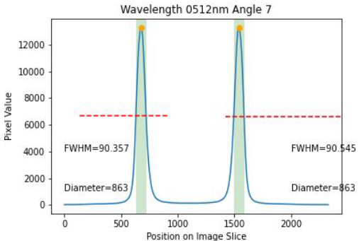
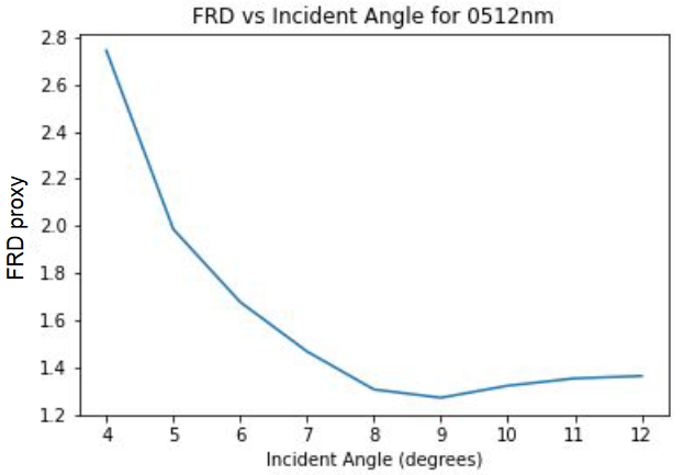
The image is rotated and this process is repeated to ensure precise measurement. The peak of each FWHM is found, and the difference between their pixel position is used as the diameter. The FRD proxy is then calculated by dividing the sum of the FWHMs by the diameter and multiplying by the incident angle2.

Once the exposure for each wavelength and incident angle is analyzed, the script produces a graph of FRD vs. incident angle for each wavelength.
Publications
Characterization of Focal Ration Degradation in Optical Fibers for Use in Astronomical Instruments, Hudson Malone, Noah Siebersma, Luke Schmidt, 2024 AggieSTAAR and Texas A&M LAUNCH poster session
Utilizing a High Power Broadband Light Source to Characterize the Throughput Ratio of Fiber Optics, Noah Siebersma, Hudson Malone, Luke Schmidt, 2024 AggieSTAAR and Texas A&M LAUNCH poster session