Flat Field Screen
Emily Boster
Project Supervisors: Jean-Philippe Rheault, Don W. Carona
Status: Complete
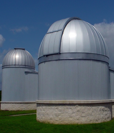
Dome data:
Data for Flat Fielding Screens
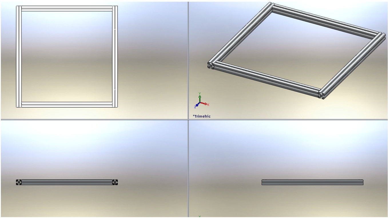
Square Frames
Texas A&M had designed larger flat fielding screens for certain Chilean observatories in rectangular shape using frame components from ITEM. For simplicity, it was decided that square frames would be used for the Texas A&M flat fielding screens. These would be constructed from ITEM Basic Elements” Profile 6 30X30 light. The length of the sides of the squares were chosen in proportion to the size of the diameter of the respective telescope that each screen would accompany. For the 16 inch telescope, a 22 inch screen was chosen. For the 20 inch telescope, a 26 inch screen was chosen. These dimensions were chosen primarily because these sizes allow for images to be taken without too great of precision in positioning the telescope. They were chosen also in consideration of the screen material that was available. Using an existing flat fielding screen in the lab, these sizes could be cut out and a new screen would not have to be ordered. The frames were ordered in September, 2010 and received in October, 2010.
Mounting Gear Design
This design was altered over the course of the project, with the final design retaining the key elements of the original concept; that is, a partially permanent mounting apparatus, while features were added to make adjustment of the screen simple. These features include the following:
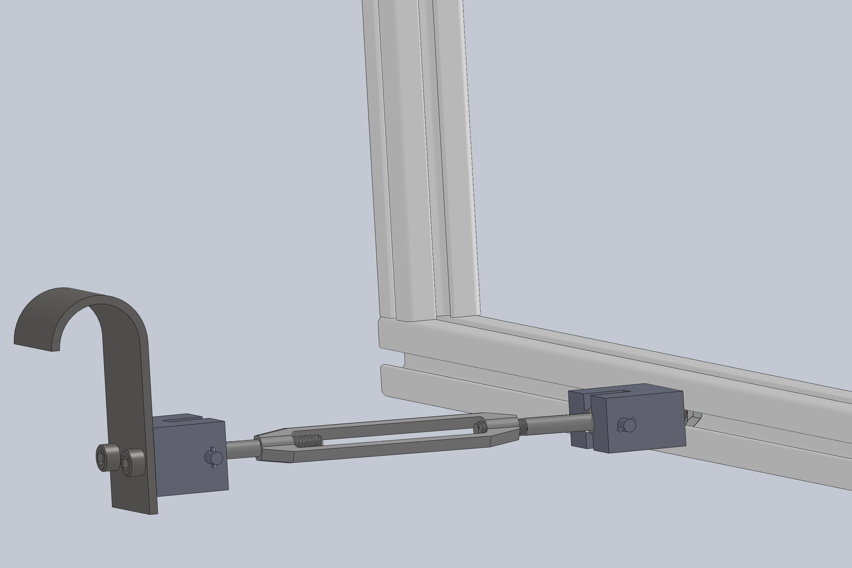
- Turnbuckle with rod ends (attached to lower part of screen for outward pitch);
- Single Hook attached to dome at lower part of screen;
- Hinges attached to (two) hooks (top part of screen to allow for curvature of dome);
- Custom Attachment Blocks to hold rod ends to respective surface;
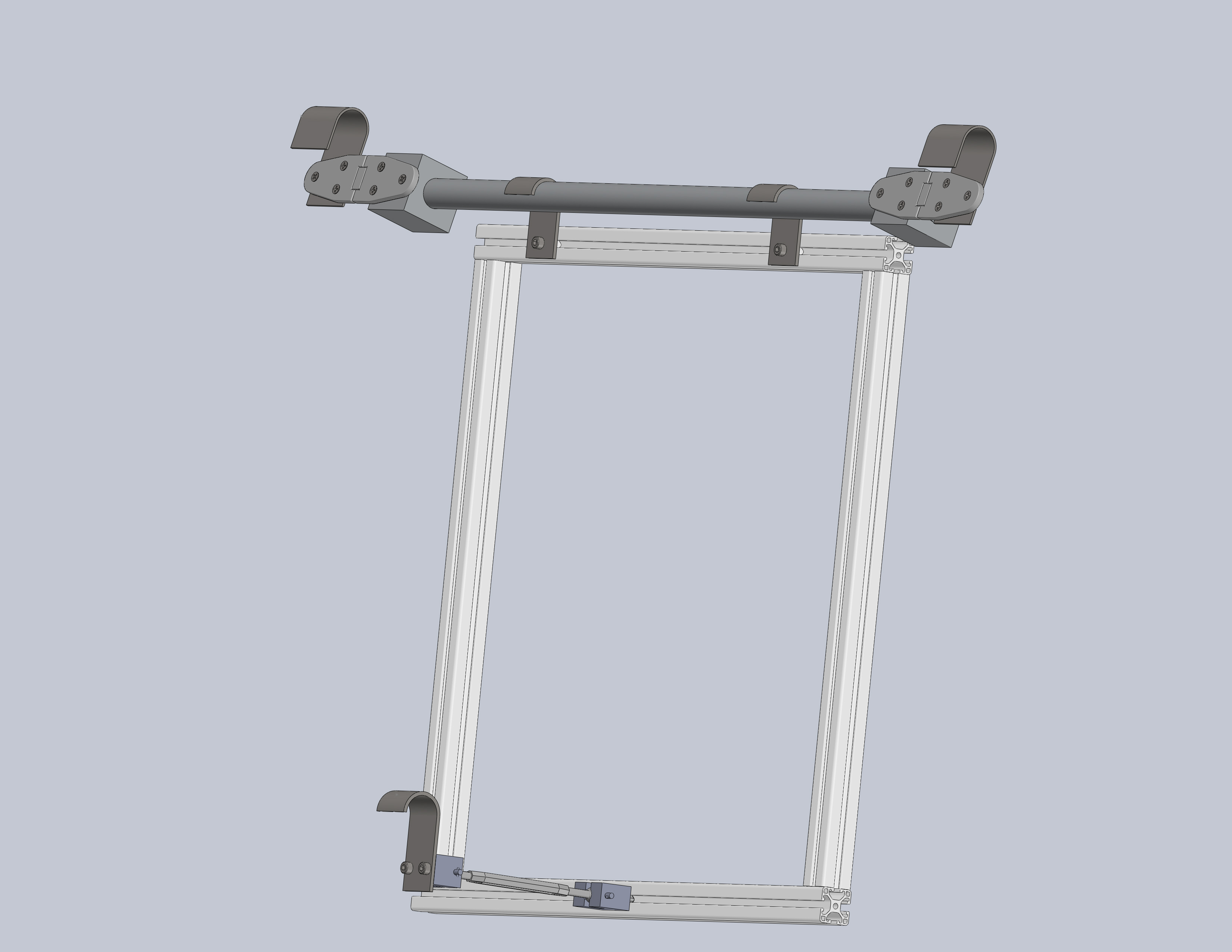
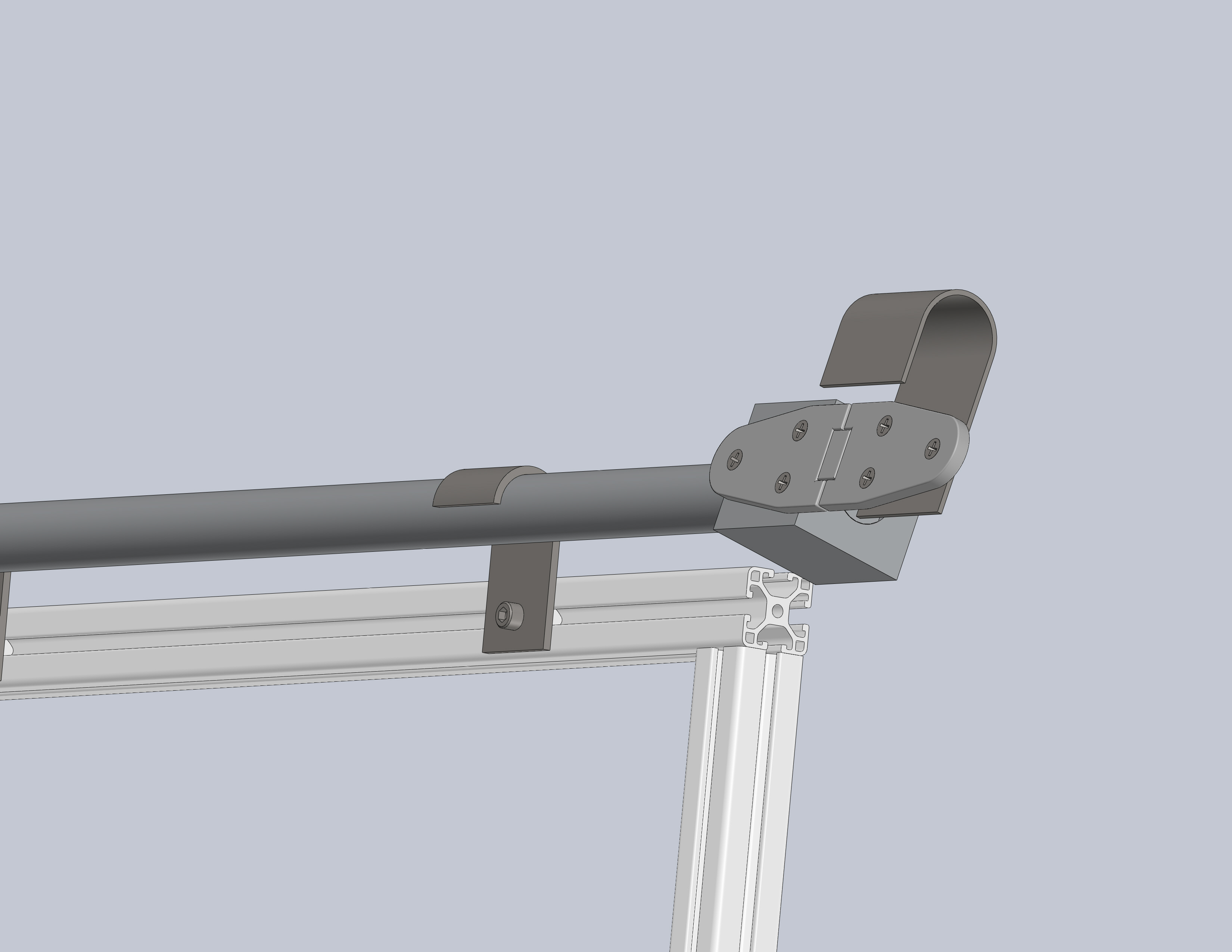
This assembly will be used for both flat fielding screens. A complete parts list can be found here.
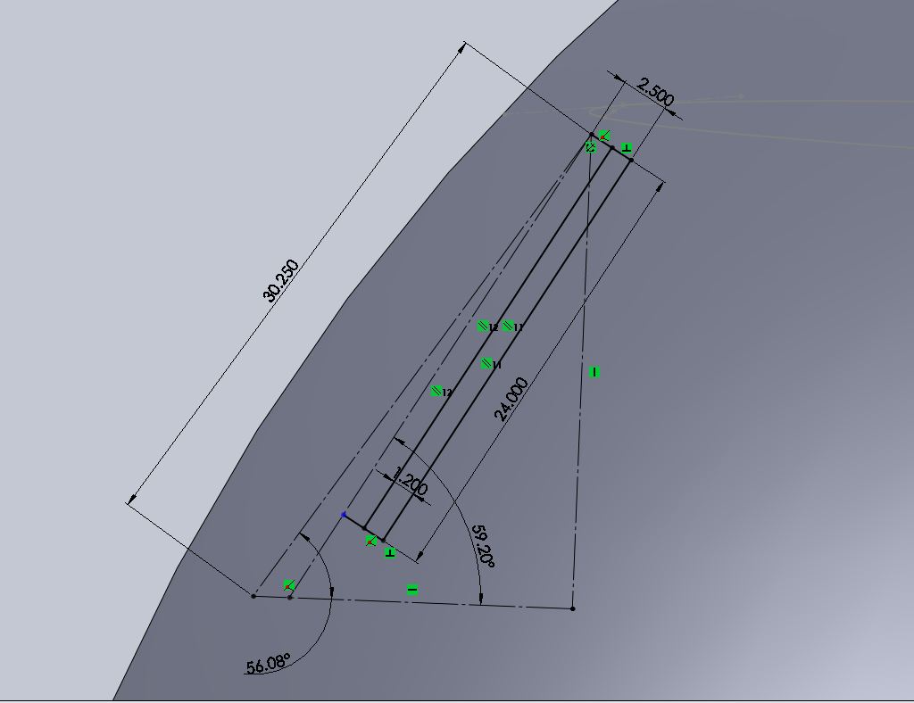
Part sizes and configurations were determined though direct measurement of the domes, solidworks measurements of actual-size model of domes, and part availability. McMaster solidworks files were used for the assembly. They can be accessed below:
- Hinge
- Rod End Left Thread
- Rod End Right Thread
- Turnbuckle
Custom parts were made to fit McMaster parts.
Design Process
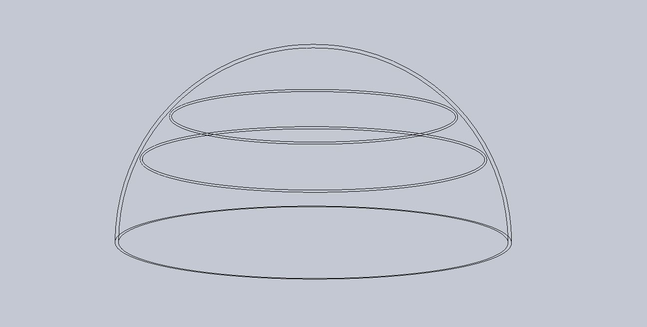
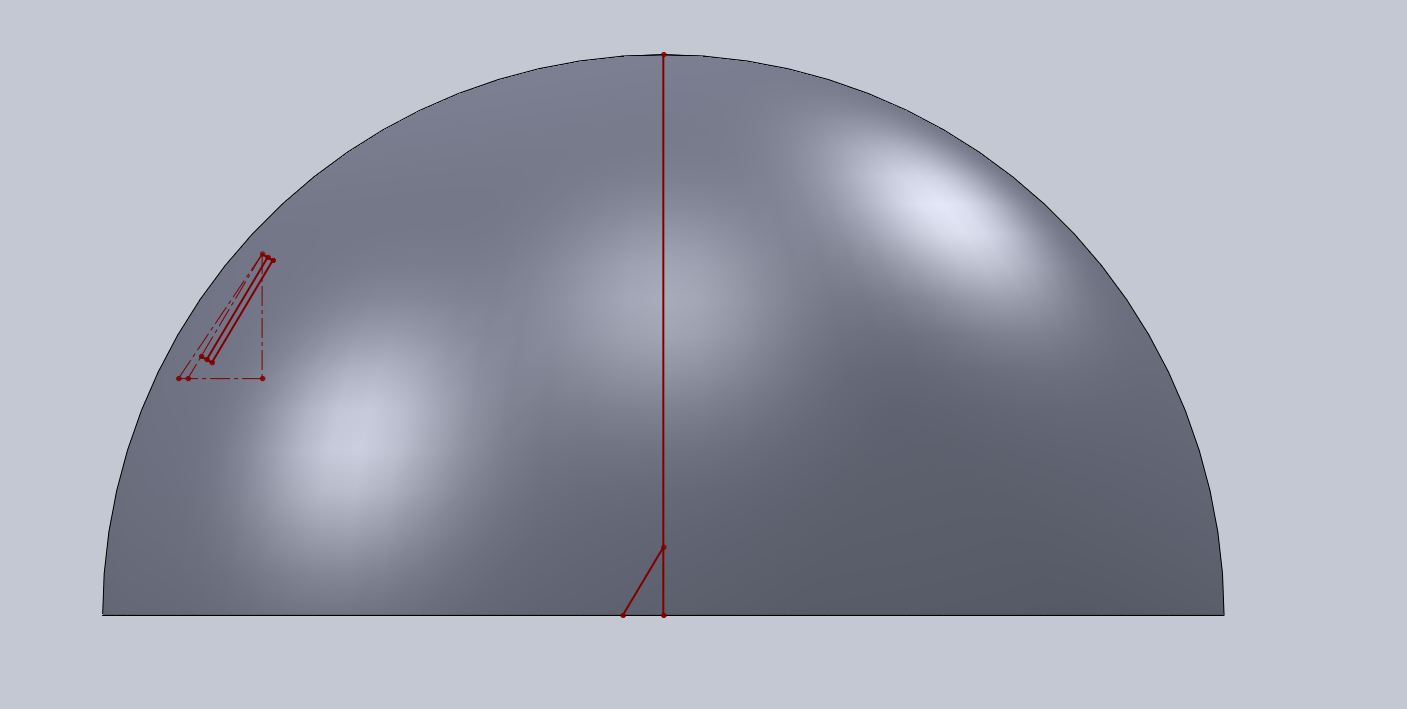
After measurements were taken of the domes, Solidworks models were built to depict the area where the screen would be mounted and to take additional measurements from. All of the following images and information is from the 18.5 diameter dome.
Machining Parts
Custom parts were made to comply with purchased parts. There were 14 total for both assemblies. These can be viewed in the parts list document. The parts were made in the AIG machine shop. Rick Allen and Emily Boster did the fabrication and machine work.
Installation
When the frame assemblies were ready, they were taken out to the observatory, and tested. The frames attached as designed, but it became apparent that the large hinge hooks would not be sufficient. The curvature of the dome along with the weight of the assembly caused the hooks to sit at an angle on the pipe ring-not fully grasping it. This problem could be fixed by elongating the end of the hook so that even at an angle, the hook would still grasp the pipe ring, or by hooking onto the pipe ring backwards. After consideration, it was determined that the most efficient thing to do was to place the hooks backwards on the pipe ring, utilizing the dome wall as a support mechanism to hold the hooks in place and prevent any movement.